Repairing a Nissan U13 Altima/Bluebird speedo
This post has come from a large amount of time diagnosing and repairing the Speedo from a 1992 Nissan Bluebird U13.
My speedo first started failing intermittantly. It started by every now and then saying that we were doing 60km/h, no matter what speed we were actually travelling. Over time it faulted more often until the point where it never showed the speed correctly. Meanwhile, my Odometer kept ticking over at the correct pace. This ruled out the Vehicle Speed Sensor (VSS) as both the Odometer and the Speedo are run off the same sensor.
After LOTS of searching on the Internet, I found that it was a VERY common problem, and that most people fix it by replacing their speedo. This is an ok solution, but can be costly, and your Odometer ends up having the wrong reading. The other option is to take the speedo to an auto-electrician, but again, this can be quite an expensive exercise.
Side Note: If your Speedo AND your Odometer fail at the same time, the first thing to do is make sure that the signal from your VSS is getting to your speedo, but this is beyond what is covered on this page.
First of all, I must state that if you follow these instructions to try and repair your speedo yourself you run the risk of damaging it permanently beyond repair. It is highly recommended that you take it to a reputable auto-electrician who will be able to repair it for you, however if you do have a good understanding of soldering and general electronics, and wish to try this out, you do so at your own risk.
Diagnosing the speedo
Remove the speedo from the dashboard cluster.
The speedo is powered by the 12 Volt ignition power supply in the car so we need to find a suitable 12V regulated power supply to diagnose the problem. I connected my speed up to a 12V power supply from an old (expendable) computer of mine.
Using aligator clips, puncture the power wires on the black (ground) and yellow (12V) wires of a hard drive power connector on the computer. Using a multimeter, turn on the computer and confirm that you have 12V DC coming out of this connection. Turn off the computer before continuing!

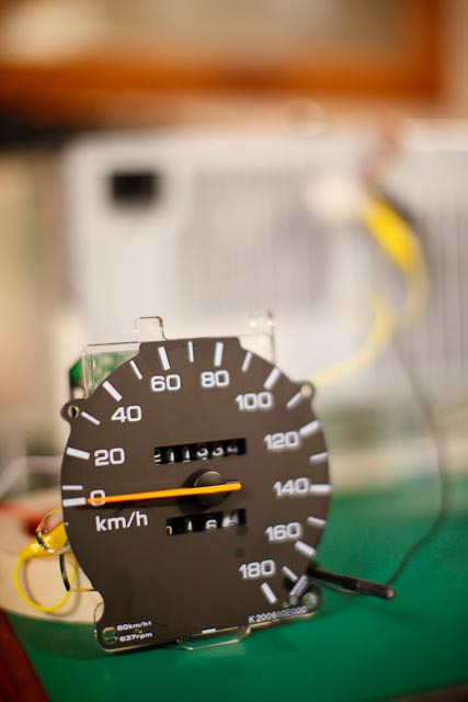
Connect the other end of the clips to your speedo (put the screws that held the speedo to the dashboard cluster into the back of the speedo to allow easy connection of the aligator clips). My speedo was labelled IGN (Ignition) which I connected the Yellow wire to (12V) and GND (Ground) which I connected the Black wire to (Ground).
Remove the Vehicle Speed Sensor from your car. This was pretty straight forward. It was on the back side of the engine (when looking from the front of the car), and located near the center of the width of the car. It had a single screw holding it in.

Connect two aligator clips to the VSS - making sure they aren't shorted together. It doesn't seem to matter which way around they go. Connect the multimeter to the other end of the leads and switch the multimeter to measure AC Volts. Spin the VSS - when you spin it, a voltage should register on the Multimeter.
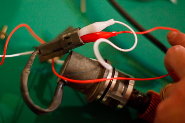
Connect the other ends to the speedo. Connect the white to the black (ground). Connect the Red to the SIG (Signal) connection on the speedo. There is a fourth screw that goes into the back of the speedo, I believe this is the feed that goes to the ECU, so there will be no connection to that while troubleshooting.

Get a bicycle with a smoothish tyre and turn it upside down...
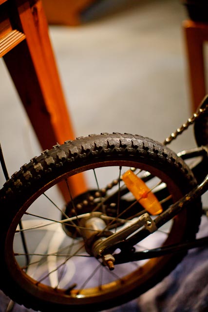
Turn on the computer power (or your regulated 12V power supply) and place the VSS on the tyre of bicycle. Get someone to help you by slowly starting to turn the pedals. Don't go too fast, as it doesn't take much speed to go as fast as your speedo goes and this may damage the speedo (no idea if it would, but I certainly wouldn't try it). If your Odometer still worked correctly in your car, your odometer should start turning over. If your speedo got 'stuck' on 60km/s (or elsewhere), or didn't go at all, it should do the same as it did in the car.

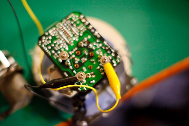
Use a combination of heating and freezing to pinpoint the problem. I started heating the circuit board with a small hairdryer, and all of a sudden the speedo started working properly. The board got relatively hot. Make sure you avoid the front of the speedo and the Odometer area. I don't know what temperature they would need to start melting (or be damaged), but I certainly didn't want to find out!

With a can of Electronic Freeze Spray, cool down the circuit board in sections and see if the speedo stops working (or alternatively starts working - you may find that cold, rather than heat, makes your speedo start working and that heat stops it again).


My failure was at the very top of the row of surface mount capacitors that you can see top-centre in the picture below. When I heated the board up in that area the speedo started working, when I froze it, it failed again. I was able to start in a general area then get very specific about which part I was cooling down.
The problem ended up being a dry joint on the board, although I was told by our local electronics guy that you can troubleshoot capacitors using the same method. I read on the Internet that some people's problems with their Speedo is caused by a failed capacitor, so it might be worth a try to heat and cool the electrolitic capacitors on the top of the board if you can't pinpoint anything on the board itself.
Resolder any solder joints on the circuit board in the area that you identify with heating and cooling (it is important that you know how to solder correctly so that you don't damage any components). You should now be able to do the above tests with heating and cooling and the speedo should no longer fail.

I hope this helps someone out there!
If this has helped you, or if you have any suggestions or comments, email pjjones at this domain.